1. Prepare
- Maixduino
- LCD 320×240
- Camera
2. Enable LvGl
LvGl is not enabled as default module in Maixduino firmware. Go to this post to enable LvGl and rebuild firmware

3. Usage
3.1 Init LvGl
LCD module must be initialized before initializing LvGl. LCD can be rotated well but it will be bug if you want to rotate GUI based on LvGl. Therefore, this tutorial keeps LCD angle as 0 degree (no rotation).
# Init LCD
lcd.init(freq=15000000)
lcd.rotation(0)
lcd.clear()
# Init LvGl
lv.init()
disp_buf1 = lv.disp_buf_t()
buf1_1 = bytearray(320*10)
lv.disp_buf_init(disp_buf1,buf1_1, None, len(buf1_1)//4)
disp_drv = lv.disp_drv_t()
lv.disp_drv_init(disp_drv)
disp_drv.buffer = disp_buf1
disp_drv.flush_cb = lv_h.flush
disp_drv.hor_res = 320
disp_drv.ver_res = 240
lv.disp_drv_register(disp_drv)
scr = lv.obj()
# Set background color
scr_style = lv.style_t(lv.style_plain)
scr_style.body.main_color = lv.color_hex(0)
scr_style.body.grad_color = lv.color_hex(0)
scr.set_style(scr_style)
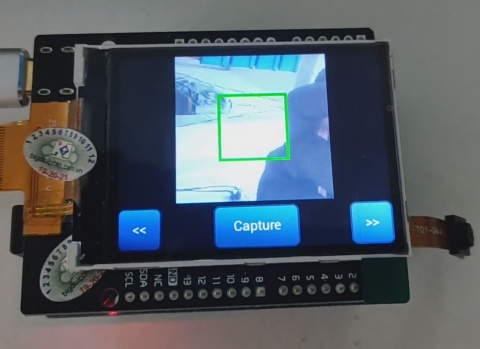
3.2 Add buttons and image frame to screen
# Add elements to screen
# Capture button
btn_capture = lv.btn(scr)
btn_capture.set_size(100,50)
btn_capture.align(lv.scr_act(), lv.ALIGN.IN_BOTTOM_MID, 0, 0)
label_capture = lv.label(btn_capture)
label_capture.set_text("Capture")
label_capture.set_size(20,20)
# Left button
btn_left = lv.btn(scr)
btn_left.set_size(50,50)
btn_left.align(lv.scr_act(), lv.ALIGN.IN_BOTTOM_LEFT, 0, 0)
label_left = lv.label(btn_left)
label_left.set_text("<<")
label_left.set_size(50,50)
# Right button
btn_right = lv.btn(scr)
btn_right.set_size(50,50)
btn_right.align(lv.scr_act(), lv.ALIGN.IN_BOTTOM_RIGHT, 0, 0)
label_right = lv.label(btn_right)
label_right.set_text(">>")
label_right.set_size(50,50)
# Image frame
video = lv.img(scr)
video.align(scr, lv.ALIGN.IN_TOP_LEFT, (320 - (240-55))//2, 0)
# Reload screen
lv.scr_load(scr)
3.3 Timer for renderring LvGl
Timer interval should be based on FPS of capturing.
# Camera frame speed
camera_fps = 30
# LvGl render interval
timer_period = 1000//camera_fps
# Timer counting flag for other functions
timer_flag = 0
def on_timer(timer):
    global timer_flag
    global timer_period
    timer_flag = timer_flag + 1
    # Notice to LvGL that timer_period passed
    lv.tick_inc(timer_period)
# Activate timer
timer = Timer(Timer.TIMER0, Timer.CHANNEL0, mode=Timer.MODE_PERIODIC, period=timer_period, unit=Timer.UNIT_MS, callback=on_timer, arg=None)
3.4 Main function
# Main task
led_state = 0
# Target rect 50x50 center of QVGA.
target_rect = [(224-100)//2, (224-100)//2, 100, 100]
while True:
    # Capture camera
    snapshot = sensor.snapshot()
    # Draw target rectangle
    snapshot.draw_rectangle(target_rect,color=(0,255,0),thickness=5)
    # Resize to fit into image frame on screen
    snapshot = snapshot.resize(240-55,240-55)
    video_data = snapshot.to_bytes()
    video_dsc= lv.img_dsc_t({
        'header':{
            'always_zero': 0,
            'w':snapshot.width(),
            'h':snapshot.height(),
            'cf':lv.img.CF.TRUE_COLOR
        },
        'data_size': len(video_data),
        'data': video_data
    })
    video.set_src(video_dsc)
    lv.task_handler()
    if timer_flag > (500//timer_period):
        timer_flag = 0
        led_state = ~led_state
        led_rgb(1,1,led_state)
    gc.collect()
3.5 Full script
Full script can be found at https://github.com/bigdolphin/maixduino/tree/main/examples_micropython
# Notice: LvGl must be enabled in firmware
import sensor, image, time, lcd, gc, micropython
import lvgl as lv
import lvgl_helper as lv_h

from fpioa_manager import fm
from board import board_info
from machine import Timer

###################################
print('\n-----------------------------')
# Check frequencies and overclock
import gc, micropython
from Maix import freq, GPIO, utils
from machine import reset

cpu_frq, kpu_frq=freq.get()
print("\nCPU Frq = %d MHz" % (cpu_frq))
print("KPU Frq = %d MHz" % (kpu_frq))

if cpu_frq != 546 or kpu_frq != 450:
    print("Removing old frequency...")
    os.remove("freq.conf")
    print("Overclocking CPU to 546 MHz and KPU to 450 MHz...")
    # kpu frequency is pll1/kpu_div
    freq.set (cpu=546, pll1=450, kpu_div=1)

gc.enable()
gc.collect()
gc.threshold(gc.mem_free() // 4 + gc.mem_alloc())
micropython.mem_info()
mem_heap = utils.gc_heap_size()
heap_free = utils.heap_free()
print("Heap size: %d bytes, free: %d bytes" % (mem_heap,heap_free))
if mem_heap != 393216:
    print("Decreasing GC heap size...")
    utils.gc_heap_size(393216)
    reset()
print('-----------------------------')
###################################

# Register GPIO
fm.register(board_info.LED_R, fm.fpioa.GPIO0)
fm.register(board_info.LED_G, fm.fpioa.GPIO1)
fm.register(board_info.LED_B, fm.fpioa.GPIO2)
led_r=GPIO(GPIO.GPIO0, GPIO.OUT)
led_g=GPIO(GPIO.GPIO1, GPIO.OUT)
led_b=GPIO(GPIO.GPIO2, GPIO.OUT)

# Function to control RGB led
def led_rgb(r,g,b):
    led_r.value(r)
    led_g.value(g)
    led_b.value(b)

# Function to init camera sensor
# Maixduino can also work with OV5640
def init_sensor():
    sensor.reset()
    sensor.set_pixformat(sensor.RGB565)
    sensor.set_framesize(sensor.QVGA)
    # set to 224x224 input
    sensor.set_windowing((224, 224))
    sensor.set_vflip(0)
    sensor.set_hmirror(0)
    sensor.run(1)
    sensor.skip_frames(30)

# Camera frame speed
camera_fps = 30
# LvGl render interval
timer_period = 1000//camera_fps
# Timer counting flag for other functions
timer_flag = 0
def on_timer(timer):
    global timer_flag
    global timer_period
    timer_flag = timer_flag + 1
    # Notice to LvGL that timer_period passed
    lv.tick_inc(timer_period)

led_rgb(0,1,1)
clock = time.clock()

# Init LCD
lcd.init(freq=15000000)
lcd.rotation(0)
lcd.clear()
# Init LvGl
lv.init()
disp_buf1 = lv.disp_buf_t()
buf1_1 = bytearray(320*10)
lv.disp_buf_init(disp_buf1,buf1_1, None, len(buf1_1)//4)
disp_drv = lv.disp_drv_t()
lv.disp_drv_init(disp_drv)
disp_drv.buffer = disp_buf1
disp_drv.flush_cb = lv_h.flush
disp_drv.hor_res = 320
disp_drv.ver_res = 240
lv.disp_drv_register(disp_drv)
scr = lv.obj()
# Set background color
scr_style = lv.style_t(lv.style_plain)
scr_style.body.main_color = lv.color_hex(0)
scr_style.body.grad_color = lv.color_hex(0)
scr.set_style(scr_style)

init_sensor()
led_rgb(1,0,1)

# Add elements to screen
# Capture button
btn_capture = lv.btn(scr)
btn_capture.set_size(100,50)
btn_capture.align(lv.scr_act(), lv.ALIGN.IN_BOTTOM_MID, 0, 0)
label_capture = lv.label(btn_capture)
label_capture.set_text("Capture")
label_capture.set_size(20,20)
# Left button
btn_left = lv.btn(scr)
btn_left.set_size(50,50)
btn_left.align(lv.scr_act(), lv.ALIGN.IN_BOTTOM_LEFT, 0, 0)
label_left = lv.label(btn_left)
label_left.set_text("<<")
label_left.set_size(50,50)
# Right button
btn_right = lv.btn(scr)
btn_right.set_size(50,50)
btn_right.align(lv.scr_act(), lv.ALIGN.IN_BOTTOM_RIGHT, 0, 0)
label_right = lv.label(btn_right)
label_right.set_text(">>")
label_right.set_size(50,50)
# Image frame
video = lv.img(scr)
video.align(scr, lv.ALIGN.IN_TOP_LEFT, (320 - (240-55))//2, 0)
# Reload screen
lv.scr_load(scr)
# Activate timer
timer = Timer(Timer.TIMER0, Timer.CHANNEL0, mode=Timer.MODE_PERIODIC, period=timer_period, unit=Timer.UNIT_MS, callback=on_timer, arg=None)
###################################
# Main task
led_state = 0
# Target rect 50x50 center of QVGA.
target_rect = [(224-100)//2, (224-100)//2, 100, 100]
while True:
    clock.tick()
    # Capture camera
    snapshot = sensor.snapshot()
    # Get real FPS
    fps =clock.fps()
    lcd.draw_string(2,2 ,("%2.1ffps" %(fps)),lcd.WHITE,lcd.BLACK)
    # Draw target rectangle
    snapshot.draw_rectangle(target_rect,color=(0,255,0),thickness=5)
    # Resize to fit into image frame on screen
    snapshot = snapshot.resize(240-55,240-55)
    video_data = snapshot.to_bytes()
    video_dsc= lv.img_dsc_t({
        'header':{
            'always_zero': 0,
            'w':snapshot.width(),
            'h':snapshot.height(),
            'cf':lv.img.CF.TRUE_COLOR
        },
        'data_size': len(video_data),
        'data': video_data
    })
    video.set_src(video_dsc)
    lv.task_handler()
    if timer_flag > (500//timer_period):
        timer_flag = 0
        led_state = ~led_state
        led_rgb(1,1,led_state)
    gc.collect()

Leave a Reply